
Paintrobot „Bob Rob“ – kann ein Roboter Kunst schaffen?
Lesen Sie hier den technischen Bericht über das Paintrobot“-Projekt in englischer Sprache. Der Industrieroboter „UR5“ von Universal Robots wurde derart ausgestattet, dass er spezifisch vorbereitete Vektorgrafiken auf die Leinwand bringen kann. Die Methode kann auch auf andere Modelle angewandt werden. Der Quellcode und die benötigten Vorlagen für Laserschnitt und das Malwerkzeug stellen wir der Öffentlichkeit zur Verfügung.
Wovon träumen Roboter? Würden sie gern elektrische Schafe malen? Finden Sie es heraus…
II. ROBOTICS BACKGROUND
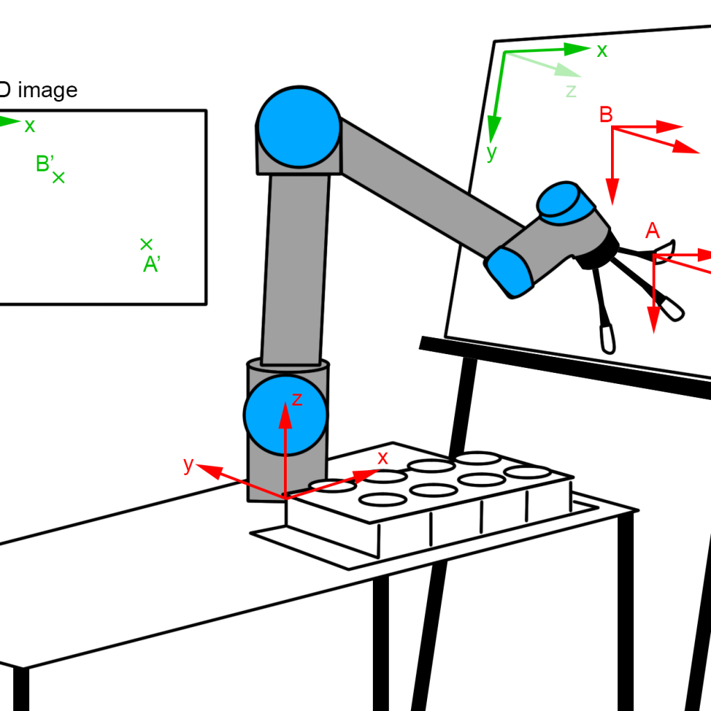
The underlying problem is explained in Figure 1 and is wellknown for everybody with a background in robotics or similar fields. We summarize the main facts here in order to enable the usage of the library for people from other backgrounds and give further reading tips. We are really trying to use not more than the inimal amount of math, which suffices to get a basic understanding and is equired to be able to modify the source code.
First of all, it is important to understand that the source image (displayed on the left top side) is a 2D image with a x and a y axis (displayed in green). But the canvas is a 3D object, which has a position and orientation in the three dimensional space. The challenge, which is solved in the svg2urx library, is to map this 2D image to the 3D canvas, so that a line in the image from point A0 to B0 (green on the 2D image) is transformed into a trajectory, on which the robot paints from A to B (in red) with the brush.
Let us consider the tip of one specific brush, which will paint on the canvas (without taking into account that the setup enables the usage of multiple brushes, we will come to this later). We call this brush tip the ‘Tool center point’ (TCP). Obviously, we need to control the position of this tip in the three-dimensional space in order to meet with a specific point on the canvas. Let us regard the situation displayed in figure 1, in which the brush tip meets a specific point on the canvas, which we call A. We assume a typical cartesian coordinatesystem with the axes x, y and z. This coordinate system has a point called origin where we start counting, so where x = 0, y = 0 and z = 0. Let’s define this at the middle of the base of the robot. (We could also position it anywhere else. In general, the robot coordinate system is distinguished from the world coordinate system, but we root both in the robot base here). Now, with this definition, the point A on the canvas can be described by the coordinates xa, ya and za, which is the distance of the point with respect to the axes measured from our base.
Paintrobot “Bob Rob” – can robots create art?
This document provides a technical report for the paintrobot’ project, which enables the industrial manipulator model ‘UR5’ by Universal Robots to paint specifically prepared vector images in .svg-files with wet paint on a canvas. The theory can of course be used for other manipulator models. The source code and the required models for laser-cutting and paint tool have been published open source [9]. What do robots dream of? Do they want to paint electric sheep? Find it out.
Index Terms: industrial robots, painting, art, open source
I. Introduction
‘Can robots create art?’ By investigating this topic for an exhibition at the German festival ‘Kunsttage Sommerhausen’, the authors came across the problem that no library for painting with an industrial manipulator has been found open source in
the internet. Especially for artist or designers, the capability to paint with a robot could be enriching and expand their current capabilities, but it is not altogether easy to implement without specific knowledge in robotics. This is why an open source framework has been created and published, so that similar projects as the paintrobot ‘Bob Rob’ can be generated in order to motivate the discussion between art and robotics. Within the expedition, in which the first installation was used (the aforementioned ‘Kunsttage Sommerhausen’), the approach has proven to stimulate a broad discussion concerning society and the possibilities of technology.
This technical report serves as an introduction to the project and a helping hand in using the framework. It briefly discusses the theoretical background of the underlying robotics problem (section one) and provide a brief overview to artistic projects with robots and artificial intelligence (section two). The used setup is described in section 3. After the specification of the currently supported vector images and possibilities to create new images are highlighted in section 4, the use of the library itself is described in section 5. The document finishes with a
summary and ideas for future work.
This position is not enough to determine the right position of the robot, because we also want to know the orientation of the brush with respect to the canvas – the brush could approach the point A from different angles. In theory, it would also be possible to approach the point from the back side of the canvas (but we definitely would not want this). In order to specify the right ‘direction’ of the brush, we can use either two positions in the three-dimensional space, or by the orientation around the axes, which is also known as roll φ, pitch θ and yaw ψ. So, if we want to describe the pose of the TCP (the brush in our example) in point A we would formulate this as (xa, ya, za, φa, θa, ψa). We call this a ‘pose’, which consists of position and orientation.
But how to come from one pose to another? Let us assume that the robot’s TCP is in pose A and the controller wants him to move to position B. In our implementation, we use the ‘UR5’ from Universal Robots, which has 6 rotational axes. All axes can be moved independently, for example manually via
the teach pendant. For further reading: If we have the position of the axes (because we manipulate them for example with the teach pendant) and want to know the resulting pose of the TCP, the mathematical equations behind this are called forward kinematics.
It is not intuitive for the novice user, to control the TCP (the brush tip) with the axis positions, but it helps to get a basic understanding of the robot. The main learning objective here is, that there are multiple ways to achieve the desired pose – the TCP most probably will not travel along the canvas (although this is what we want to achieve). Furthermore, it is not quite easy to move from one point close to the canvas to another by steering the axes, because we can in the standard mode ‘only’ manipulate the axes – the resulting circular movement around the axes is not desired.
Fortunately, the robot is able to calculate the path from A to B (instead of moving the axes manually). The robot needs to solve the so-called inverse kinematics problem, in order to determine, how it should move the axes in order to come to pose B when it already is in pose A. But there might be different ways to perform this movement, just as if it is performed manually. The robot searches for the most efficient solution. Thus, it is not a good idea to tell the robot to directly move from A to B if both points are on the canvas, because the path in between is some kind of circular movement (around the robots axes) and will most probably go through the canvas and either tear the canvas or break the brush.
After briefly explaining these problems, it is good to know, that they already have been solved. There is the possibility to switch the coordinate system, in which the TCP is moving. In our case, it is possible to calibrate the coordinate system of the canvas with respect to the robot’s coordinate system and every movement can then be specified along this coordination system (or reference frame). The calculation in the background are still the same: The inverse kinematics problem is solved in order to determine, how the axes should be rotated in order to come from one pose to another. The difference is, that the poses in the coordinate system of the canvas need first be transferred to the robot’s coordinate system.
If we want to tell the robot to paint a specific line, we need to make sure, that the orientation of the brush is known for all points. A human person would eventually slightly move the wrist so that the orientation of the brush differs. Although this is of course possible with the robot, we use the easier wayand tell the robot, that it should use the same orientation, but move the position along the coordinate system of the canvas. An analogy to this is for example a human painter, who keeps the wrist fixed, but moves the elbow, in order to paint a line. It is important to understand, that most robotics applications depend on accuracy on the one hand but also on velocity. Movement in the joint-space is faster than movement in recalculated canvas space, so it should be used for longer movements.
III. ROBOTS, AI AND ART
As explained above, the underlying problem has already been solved a long time and can be researched in the standard literature under the mentioned terms, for example in [1]. Painting with liquid color still remains an engineering problem
which strongly depends on the application [2].
A better way to produce ‘paintings’ can be achieved by 3D printing, whereas a 3D printer can also be regarded as a cartesian robot. Recent design research of TU Delft [3] showed the application of 3D printing for the reproduction of fine art. Here, 3D scanning is used to detect relief, color and gloss.
Using ‘robots’ as part of artworks has a long history, and includes ‘moving’ objects, for example the work of Jean Tinguely. Newer work naturally used the capacities of industrial robots – the German artist collective ‘robotlab’ let the robot for example generate random statements and write them down during the exhibition [4].
The next step is to use some kind of machine learning or artificial intelligence approaches instead of using randomly generated ‘art’.
In 2015, creative agency M&C Saatchi detected the face expression of people who looked at their advertisement posters. They used cameras above the digital posters and machine learning algorithms [4]. Based on people’s reactions (happy, sad, etc), the poster would try to change to a more pleasing design.
In 2018, the painting ‘Edmond de Belamy’ by Paris-based arts-collective Obvious was sold for 432,500 Dollars. The painting was generated by an open source algorithm written by the 19-year old Robbie Barrat, who is not affiliated with the artist collective [6].
Currently, there is a well-recepted exhibition under the name ‘Artists and Robots’ at the Grand Palais in Paris [7], which summarizes the historical development and raises the question, whether robots or artificial intelligence programs can really create art. Finally, there are research groups, for example Rutgers University’s Art and Artificial Intelligence Laboratory, who are investigating this topic further [8].
IV. PAINTROBOT BOB ROB
A. Setup
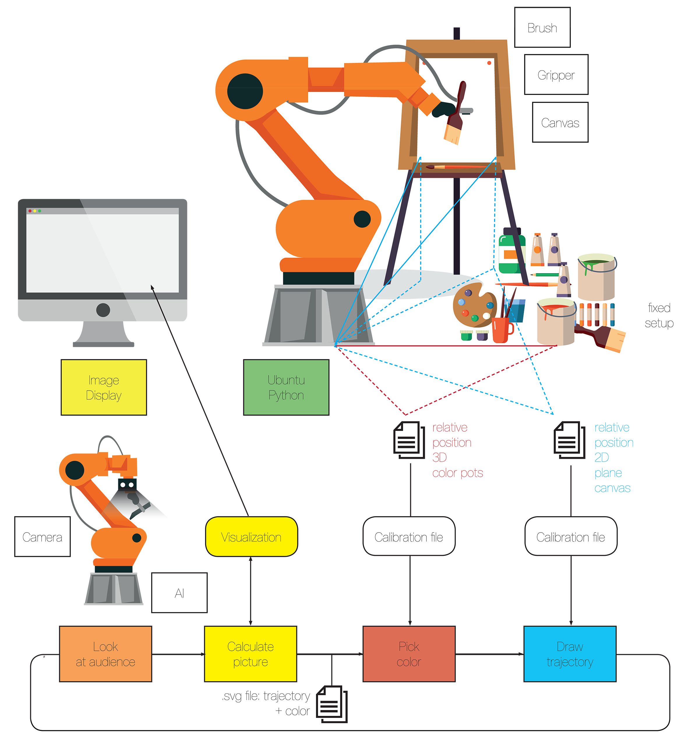
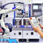
The current setup is displayed in Figure 5. The industrial manipulator ‘UR5’ by Universal Robots has a 3D-printed tool, which can hold four brushes. The source files for the tool can be found at the paintrobot page [9]. Each brush is used only for one color, so that the brushes do not need to be cleaned in between. An alternative would be to use brushes of different size. The robot will move each brush to its color cup (left bottom side), here the colors red, yellow, blue and purple are used and contained in recyclable espresso cups. Next to each color pot, a wireframe construction is placed over a second pot, where the excessive paint is removed (dripping color can be reused). The source files for the laser-cut color pot containers is published as well [9]. The robot and the color pots are fixated at the table. The canvas in this setting is contained in a steel mounting frame which is welded to the steel table, on which the robot is positioned. The canvas is screwed onto the frame.
B. Painting
The robot starts in the home position Jhome, in the configuration predefined by the manufacturer (all joints build one line, which is perpendicular to the table). The robot will collect paint for each path defined in the .svg (for more on this, read section V). For this, it moves to the position Jpaintabove on top of the color pots using a fast movement in joint space. The robot then changes to cartesian space, moves above the right color pot and dives in.
Afterwards, it removes the paint on the second pot with the wireframe construction and moves back to Jpaintabove. The robot will then move to Jcanvasabove again in joint space. From there, it will move in the pre-calibrated canvas coordinate system and drive a trajectory of the mapped positions presented in the .svg. It makes sense to arrange the .svg in such a way, that longer paths are included twice (in opposite directions). This results in the following behavior: If the path is too long, the robot will collect color a second time and drive the trajectory backwards. It is very important, to ensure that save movement between Jhome, Jpaintabove and Jcanvasabove in joint space is possible, so this should be tried out during the initial setup.
V. IMAGE SOURCES
The library is able to paint .svg files with the following properties:
- The .svg needs to have the same size as the canvas. Units need to be millimeters.
- The library only handles path elements, no transformations.
- Within a path element, only moves (M) and straight lines (H, V, L) are supported (all other movements could be implemented rather easily with the existing libraries).
- The color needs to be specified in the stroke attribute.
VI. USING THE LIBRARY
The operating PC needs a python 2.7 supporting operating system (we used Ubuntu Linux) and needs to have the used pythons libraries installed. The urx library uses the Universal Robot script language and communicates with the UR5 via LAN. The library svgpathtools is used to handle .svg graphics.
A. Calibration
It is important to re-calibrate the positions to the setup, in which they are used, or nothing will work. The brushes need to be re-calibrated when they are exchanged and also the canvas should be re-calibrated on every change.
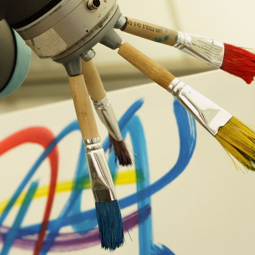
First of all, the used brushes need to be calibrated. The end of the brush is the tool center point TCP (as described above), so nothing will work, if the parameters are wrong. The brush tool is displayed in Figure 6 and is 3D-printed and mounted to the robot. All brushes need to have the same length (sawn off brushes have been used here) and are mounted on screws which are stuck through the tool. If the brush is not even on the screw, it should be moved, so that it does not change the angle between the brushes. As mentioned above, it is crucial, that a collision-free and safe movement between Jhome, Jpaintabove and Jcanvasabove is possible!
The position of the color pots Jpaintabove can be calibrated with a tape measure and adjusted by slightly changing values. As the height of the wireframe construction might change, this needs to be adjusted.
For the canvas, first of all Jcanvasabove needs to be defined. Then, the origin on the top left corner (P0) needs to be measured precisely by driving the robot to this position, so that only some hair of the brush used for the calibration touches the surface. The right left corner (P X) and the bottom left corner (P Y ) need to have exactly this same distance to the canvas, so the same brush should be used. We recommend to choose the three points with a slight offset of the 80x60cm canvas.
B. Painting program
The robot starts in the home configuration. The main function is called paint_svg(). For each path element, which is found in the loaded .svg, the following operations are performed:
- move_to_paint(): Move from Jhome to Jpaintabove)
- get_paint(): Move from Jpaintabove to the right colorpot, move into color pot (color is specified in the path element), move over color pot, wait for color to drop off and remove paint from tip of brush
- move_to_canvas(): Move from Jpaintabove to Jcanvasabove
- paint_path(): For each sub element in the path, go to this position with respect to the canvas coordinate system. The parameter ‘feed’ is used to press the brush more and more to the canvas during the movement on the path.
VII. CONCLUSION AND FUTURE WORK
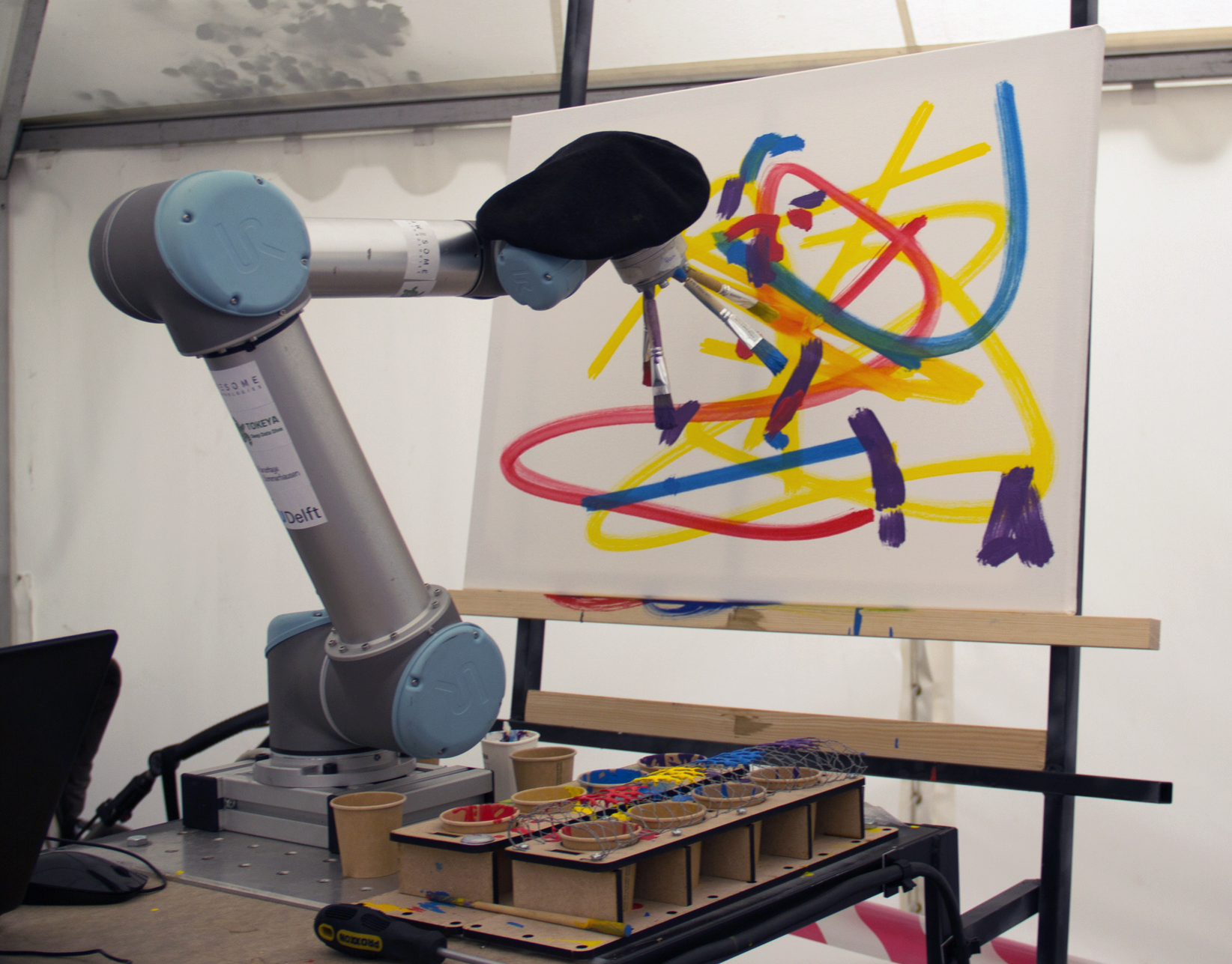
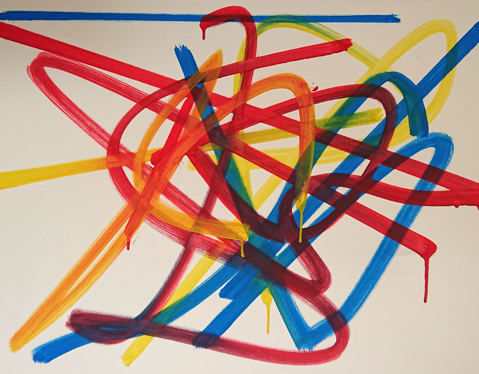
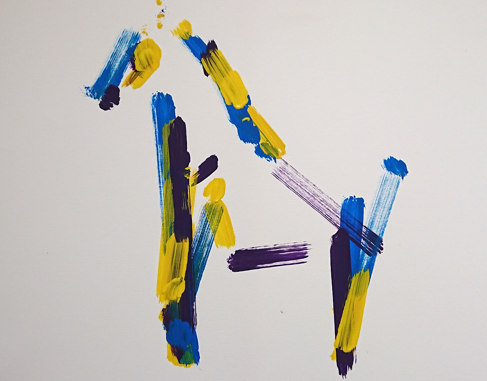
This work was conducted in a joint project initiated by the ‘Kunsttage Sommerhausen’ together with the German company ‘Awesome Technologies Innovationslabor GmbH’ and TU Delft Design Engineering. In the first exhibition of the project where the pictures above were taken, we used very basic image generation out of random variables and with some external input (for example from the webcam) provided by Tokeya Deep Data Dive. But there are many funny ways to use existing AI toolboxes with this. We are currently developing a Windows based tool chain which will be easy to use for designers and further facilitate the process of running the robot by further developing the graphical interface. We are going to use this code for future projects and for education and hope to learn from other projects who are using our framework. So if you want to collaborate on this – please contact us!
REFERENCES
- [1] Hägele, M., Nilsson, K., Pires, J. N., & Bischoff, R. (2016). Industrial robotics. In Springer handbook of robotics (pp. 1385-1422). Springer, Cham.
- [2] Chen, H., Sheng, W., Xi, N., Song, M., & Chen, Y. (2002). Automated robot trajectory planning for spray painting of free-form surfaces in automotive manufacturing. In Proceedings 2002 IEEE International Conference on Robotics and Automation (Cat. No. 02CH37292) (Vol. 1, pp. 450-455). IEEE.
- [3] W. S. Elkhuizen, T. T. W. Essers, B. Lenseigne, C. Weijkamp, Y. Song, S. C. Pont, J. M. P. Geraedts, and J. Dik. 2017. Reproduction of gloss, color and relief of paintings using 3D scanning and 3D printing. In Proceedings of the Eurographics Workshop on Graphics and Cultural Heritage (GCH ’17). Eurographics Association, Goslar Germany, Germany, 183-187.
- [4] Robotlab (2008). Exhibited in ‘Open Codes’ 20.10.2017 02.06.2019 at ZKM.
- [5] Green, Ricki (2015). M&C Saatchi London launches first ever artificially intelligent poster campaign.
- [6] Edmond de Belamy.
- [7] Spinney, Laura (2018). Can robots make art? Nature 557, 490- 491 (2018) doi: 10.1038/d41586-018-04989-2
- [8] Mazzone, M., & Elgammal, A. (2019, March). Art, creativity, and the potential of Artificial Intelligence. In Arts (Vol. 8, No. 1, p. 26).
- [9] Paintrobot Bob Rob
- [10] urx python library
- [11] svgpathtools python library
